It’s been pretty much three wasted years and I’ll probably graduate with a BSc around the age of 26.
What happened?
I was born and raised with computers and the Internet - I bought my first soldering iron at the age of 14 to add LEDs to my Xbox controller and program my first PIC microcontrollers, I learned Python and the basics of Computer Science on EdX and was trading Bitcoins in my last two years of high school. I learned English to a proficient level by browsing Reddit and chatting in IRC channels. I won an Arduino kit in a Sparkfun Free Day and started hacking around.
Of course, studying Electronics Engineering in the best university in Italy seemed like a great thing to do.
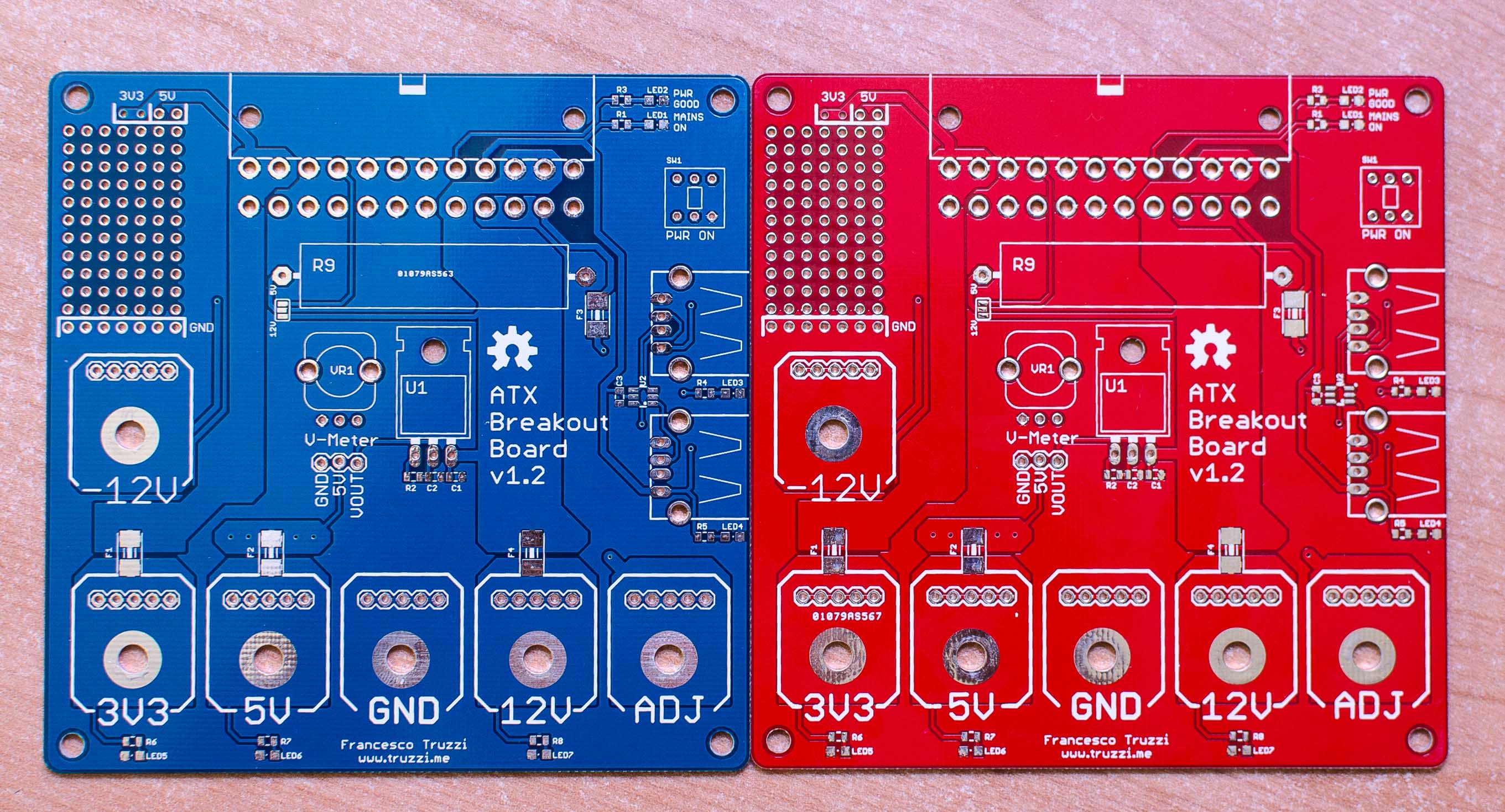
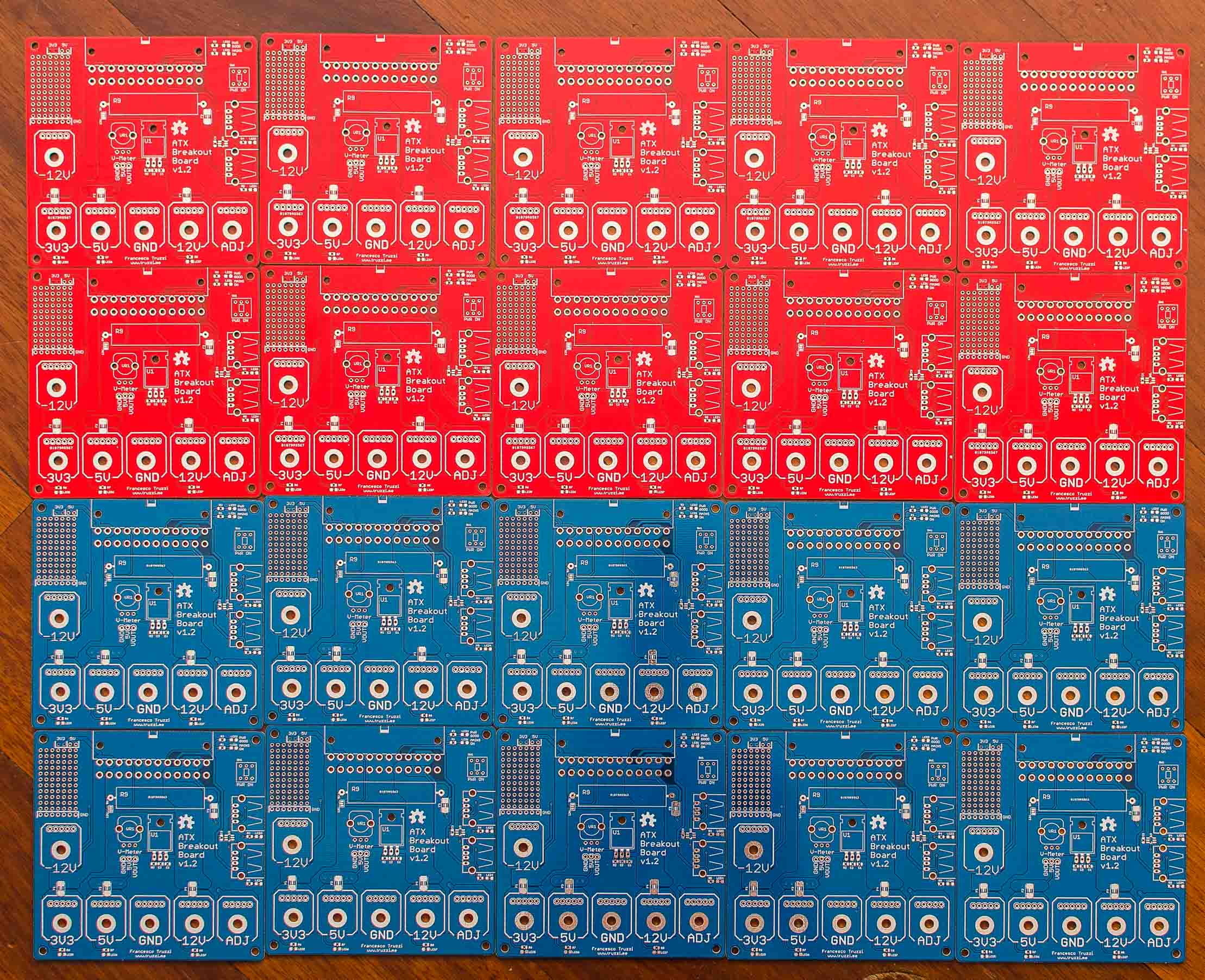
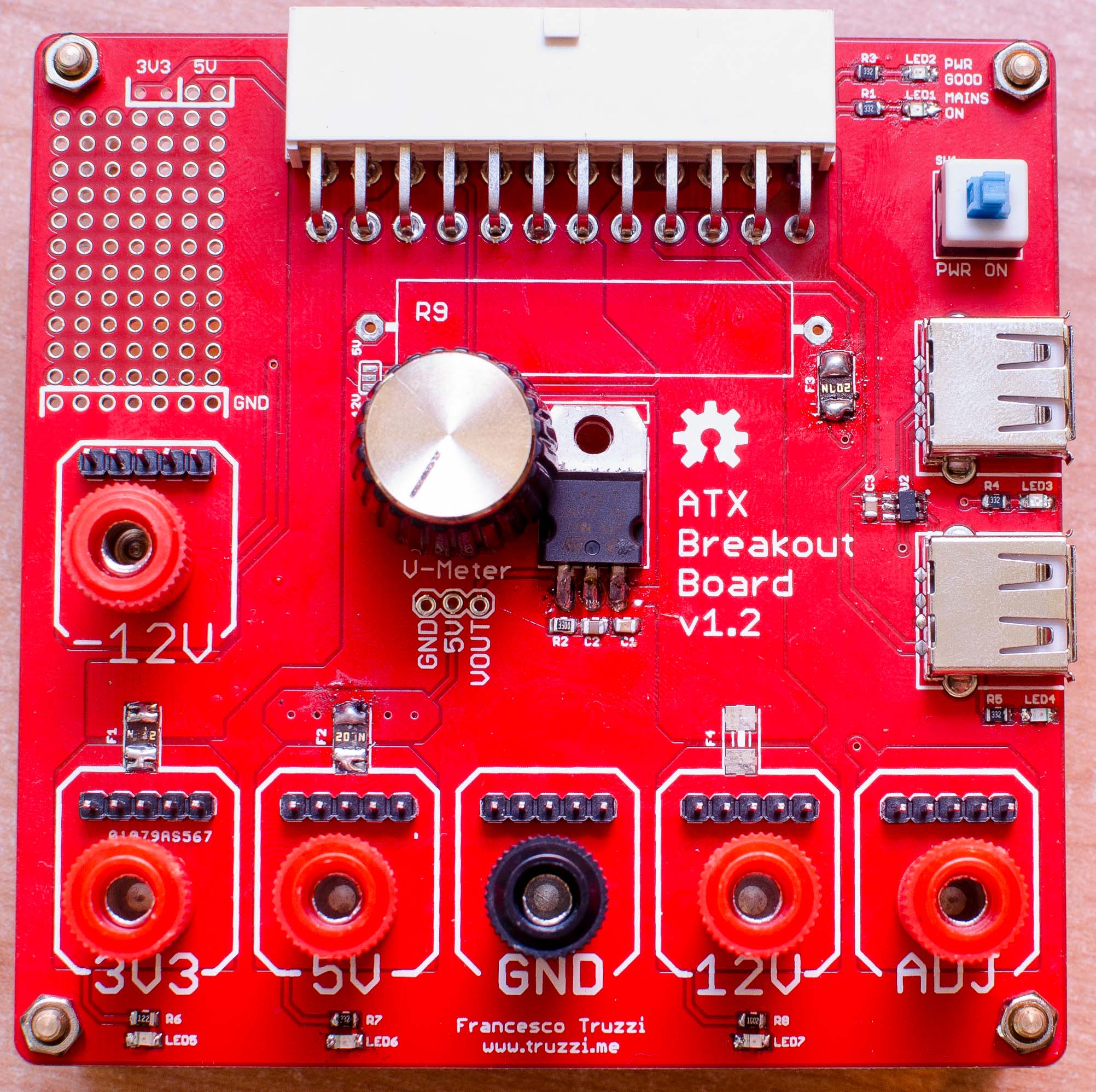
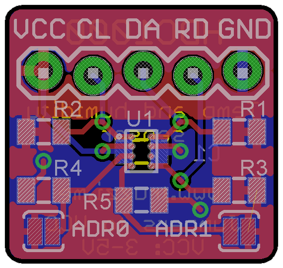
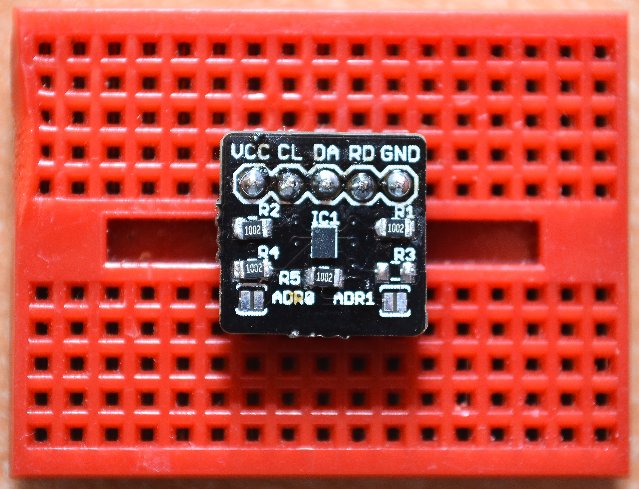
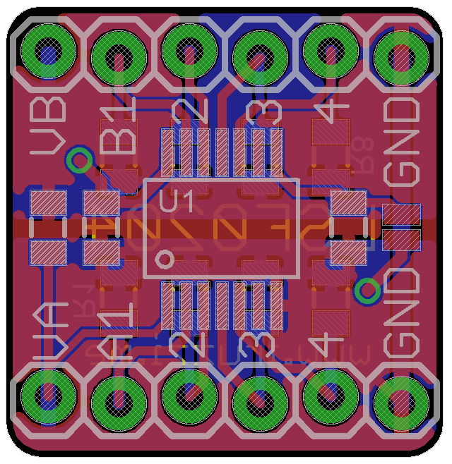
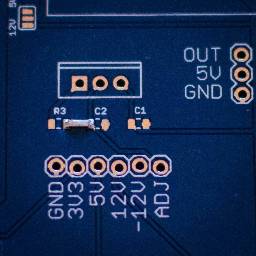
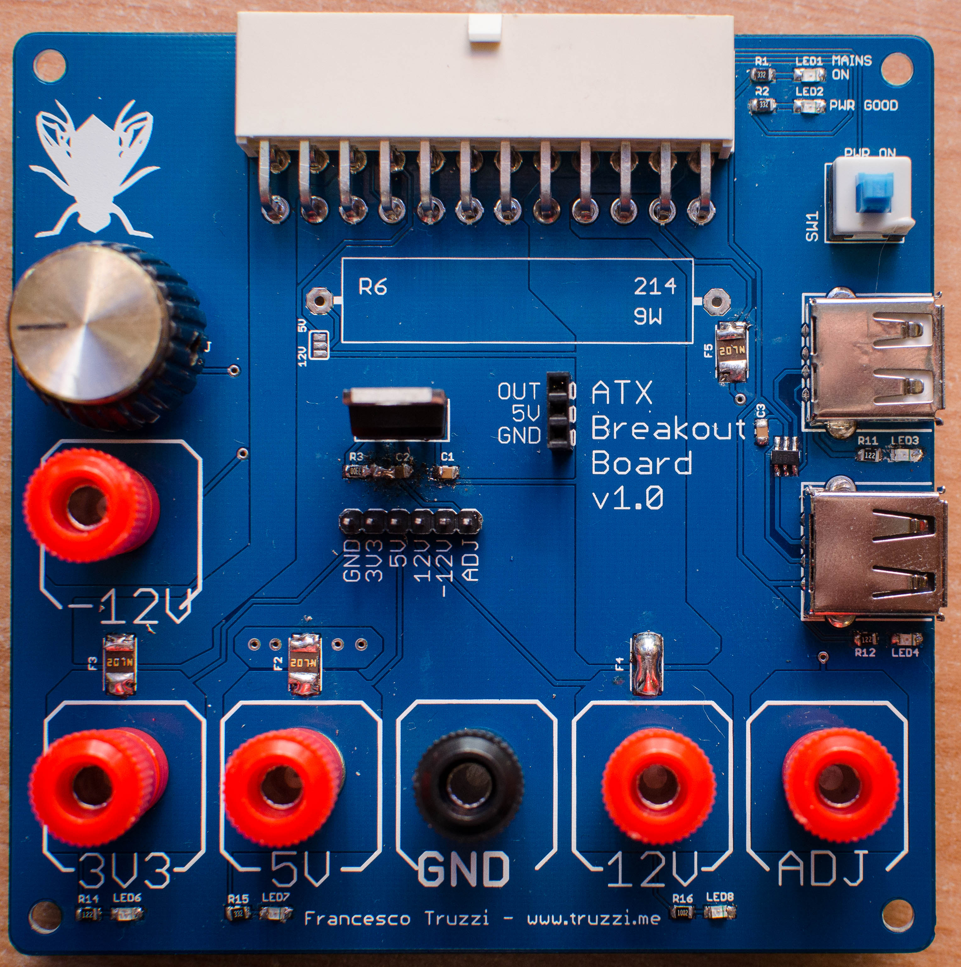
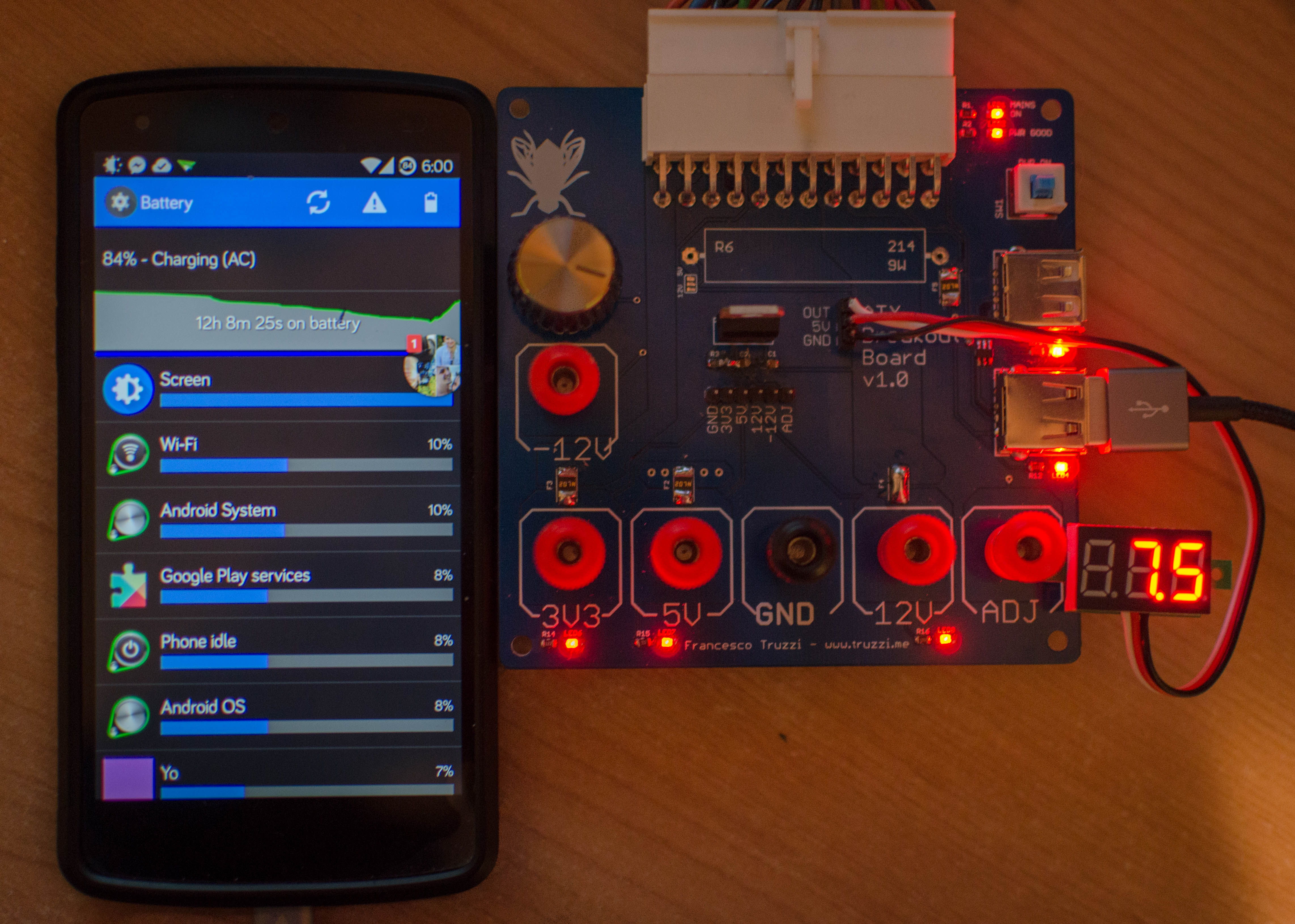
Before starting college, I bought Practical Electronics for Inventors and read it almost cover-to-cover. That summer, I learnt how to design PCBs and printed my ATX Breakout Board that for whatever reason some people still want today.
I started college as happy and motivated as anyone can be, believing I had finally found my path after six grueling years in high school. Little did I know that it would be even worse. The EE course at Politecnico had, in my opinion, all the characteristics of the way too rigorous, flattening, demotivating, passion-killing Italian school system.
In hindsight, the first half of the first year went pretty well. I aced my first two exams and nearly passed the third one. However, for the following two years, I hated the courses and I stopped attending for the majority of the time, getting bad grades in the other exams.
One sad truth that I’ve observed is that the Bachelor’s degrees (or at least the one in EE) at the Politecnico are completely useless, just a primer for Master’s degrees.
In 2017, you can’t take bright, eager, Internet-raised kids who want to learn electronics and CS and simply dump a shitload of math and physics on them for three years, without ever taking them to a lab or teaching them how to design even the most basic circuits or showing them the bases of object-oriented programming, to say one.
Don’t get me wrong, I understand the importance of math and physics in an EE curriculum. Actually, the Mathematical Analysis 1 course (think of it as Calculus 1 on steroids), taught by the incredibly good Federico Mario Giovanni Vegni, albeit hard, was the best I’ve ever taken.
On the contrary, the worst course in my career was Physics (12 ECTS), the biggest course in the whole degree without including Electromagnetism. Does it make sense to you that the most demanding course in an EE degree is one composed of just mechanics and thermodynamics? Again, I’m not saying you don’t need to know Physics, but don’t overdo it or people will just get mad and leave.
In fact, I remember walking out of that class more than five times, as I couldn’t bear the boringness of the course. I didn’t even try the exam because I couldn’t stand it and we were given no course material at all, not even solutions to the practice exercises.
When I took Basic Circuit Theory the following year, the professor announced that there would be no labs. Are you seriously teaching circuit design to people without showing them how a resistor looks like? What fucking shapes can an SMD component have? How to use an oscilloscope? In supposedly the best university in Italy? I dropped out of the class, studied Thevenin, Norton and all the course on the book and managed to pass the exam anyway, completely disgusted.
Sadly, the whole study plan is minimally customizable (just to the extent required by Italian law, so 15 credits out of 180) and there are really no interesting courses to pick from in the Bachelor programmes. You want to put something like Embedded Systems in your Bachelor’s degree? Don’t you fucking dare. Computing Infrastructures (datacenters, VMs)? Nah, that’s for Master’s degrees.
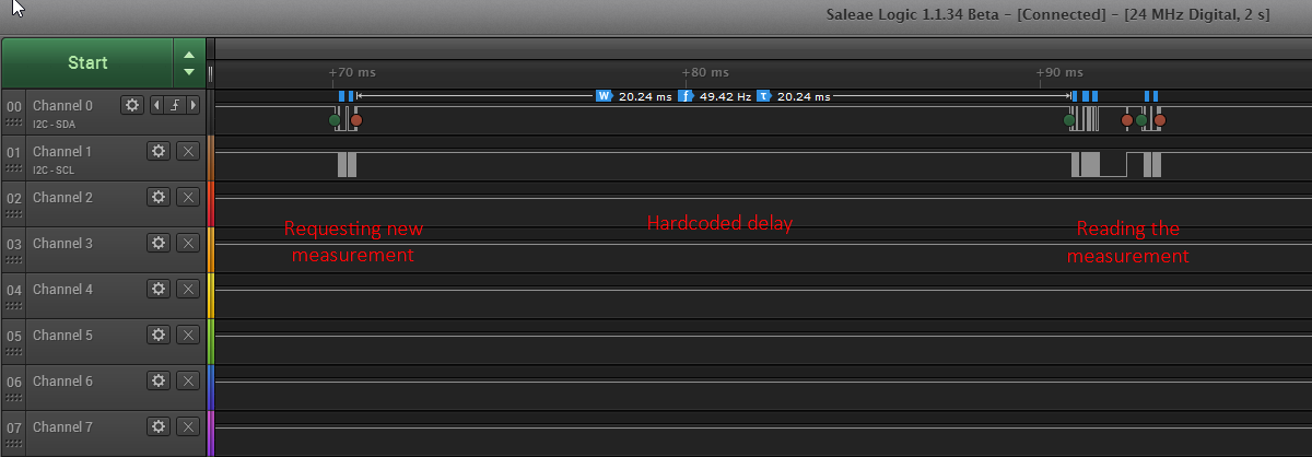
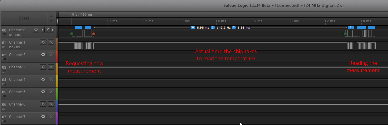
What do most people know when they finish their BSc at Politecnico? Pretty much nothing, and that’s a widely-held opinion among freshly-minted grads. For EE, do you think they have any idea of how embedded systems work? How basic communication protocols such as I2C work? Do you think they could even hover near an undergraduate hardware internship such as those offered in the US? This is a result of taking the 5-year Engineering curriculum and splitting it into 3 (BSc) + 2 (MSc) without any fucking care.
Most of the people I knew there, they’re finishing their degrees now, are just people who enrolled because of the name of the Politecnico, because it’s a degree that gives high monetary returns, or because it’s the thing you do after high school if you’re good. It’s people perfectly raised by the antiquated Italian ‘licei’ (the name for our top scientific high schools, for when science was made crossing pea plants) who just continue up the well worn path into cushy jobs without actually having the skills to do them, while wondering how come they are all using apps and websites made by foreign university graduates or dropouts. Smart people do learn on the job, but it’s hard to catch up. This can’t be a coincidence.
Of course there are exceptions to that (very brilliant people that graduated and know their way around electronics/their field much better than me) and I’ve met some, but they share at least some of these complaints with me.
I’ve always had a thing or two against authority, but the Italian supposedly ‘elite’ education system is simply suppressing people wants and needs. It’s outdated. It was born in the fascist era and didn’t evolve much. Either you do things they way they tell you, or you’re left behind. No flexibility, no listening to the needs of society, economy and people. You can’t pick any of your courses. Are you a cube? Great, I’ll push you through this round hole in the wall. My quite-well-renowned scientific high school offered zero computer science classes, zero economics classes and zero basic law classes, batching out members of what they called ‘the ruling class’ who couldn’t read a contract, understand where money comes from and goes to or do their taxes to save their lives. In their defense, it looks like they’re catching on and now offer a program with a CS class.
I hope that one day, someone will come up with an idea that crushes this system to the ground before it can even look up and realize. I truly hope that approaches like Khan Academy and Khan School are the answer and will catch on, slashing costs (and therefore accessibility) while improving quality. Bad professors can and will be replaced by on-demand videos and education will be more centralized, tailored and easier to reach. Right now, education is mainly determined by where you are born and grow up. Curricula need to be customizable and built around each student.
Schools have to stop bragging that ‘only 1/3 of students make it through here.’ Hard doesn’t mean better or more effective. In fact, if more than half of the people drop out without a degree, it is either a completely unheard-of level of student laziness or a plainly inefficient system. I would go for the latter. Learning things you like isn’t hard, no matter how tough they are. It’s fun, stimulating. It’s brain food.
The only great thing I did during these three years was an internship at Cisco, but I would say it has nothing to do with the Politecnico apart from the fact that I had to bring a university agreement. Go figure why they let me get one without passing all the exams of the first two years, but this means that I can’t get credits for it until I can put it into my study plan and that would be next year. But you know what? Fuck it. I’m quitting.
Before making this decision, I went to talk to the Dean of the EE department. He was a very nice and kind person who genuinely wanted to help me despite having never seen me. When I showed him my ATX breakout board, he half-jokingly said that I was ahead of them because nobody there knew how to do that. Was that true? Of course not, they’re professors and I’m a bad student. But they just know (and teach) the theory. His advice? Go study somewhere else where they actually make you build stuff. Go to the UK or the US. Now if only I could afford that…
I can hear you from here: “University is just meant to teach you the fundamentals, the basics, the theory. If you know the basics well, you can learn to design PCBs and circuits in a week.” - True, and that’s how I did it. We just should have both, and many (most?) universities in the US or UK do that already. They have things such as ‘senior design projects.’ We Italians have no idea of what that is. We have 100% theory and zero practice. School has to be stimulating and rewarding. If it’s boring and so detached from reality, students will just hate it. Popular pages like Ingegneria del Suicidio (Suicide Engineering) and Polimi Exhausted are two sad examples of this.
I have friends doing their Master’s at Politecnico and I believe they are far better. Courses are taught in English and there are many labs and projects, at least in Computer Science and Engineering (the study plan is very interesting), but if I have to go through three years of shit that inevitably become 4 or 5 (nobody eats shit promptly)… thanks but no thanks.
In hindsight, I probably should have enrolled in the BSc in Computer Science and Engineering, which is a course that was built more recently (they even offer an online one) and maybe isn’t stuck in the 1950s, but I wanted to learn how to build electronics stuff. Too bad they don’t teach that.
Even though I don’t have much faith left in Italian universities, I will probably transfer (read: start from scratch apart from 3-4 exams) to University of Milano-Bicocca and study Computer Science. After that, the OMSCS by Georgia Tech could be a great option. Unfortunately, Bachelor’s degrees in Europe are mainly taught in the native language of each country and application deadlines for international students are around April.
I’m quite sad, because I’m 23, have no degree and have spent 11k€ to learn nothing. No matter how I look at it, I failed (still not sure if it’s a failure of choice or execution, probably both) and I could have accepted sooner that Politecnico wasn’t my place. I could have changed school after my first year. But when I fail, I cheer myself up by telling the cautionary tale to other people and watching Jack Ma, founder of Alibaba.
The world is evolving, economies are shifting, workplaces are changing. School is lagging behind tremendously.
TL;DR: Don’t do your Bachelor’s at the Politecnico, especially in EE. Do it somewhere else and come for a Master’s.
EDITED 28/08/2017:
Many people have told me that I shouldn’t complain because this is how excellent schools work and who am I to tell the Politecnico how it should teach students. Also, fundamentals are really important and I am too immature to understand that.
Let’s take the example of two other excellent Engineering schools, the MIT and ETH Zurich. They’re considered to be even better than Politecnico.
Here is the study plan for the first year of EE at the ETH.
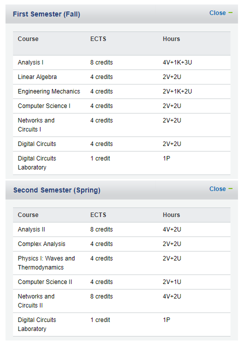
And here’s the Politecnico’s:
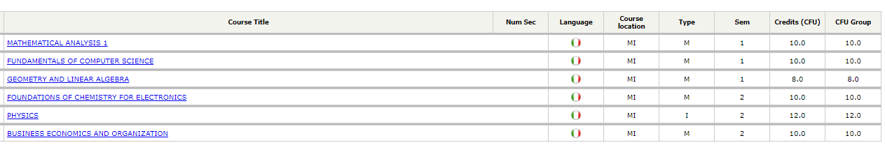
A quick comparison shows that, for example, Physics I is 4 ECTS compared to 12 at the Politecnico. Analysis I and II are 8 instead of 10, Linear Algebra 4 instead of 8.
Uh, new wild credits that can be used for Digital Circuits appear! In their first year, students at the ETH have 9 electronics labs where they implement an ALU on an FPGA. They also have at least 6 credits of laboratories, projects and seminars on their second year. At Politecnico, FPGAs are only studied in theory at the end of the third year and they seem to hate digital electronics. Now I’m waiting for someone to come and tell me the ETH is not a school of excellence.
Take a look at how they teach Operating Systems at Stanford. They have significant programming projects and I hope nobody thinks universities shouldn’t teach that.
Now, an example from MIT. Here are past exams from “6.002 - Circuits and Electronics,” the introductory course in Electronics. Here is a random exam from the “Introduction to Electronics” course at the Politecnico. The MIT exam is better structured with exercises that scale in difficulty (having many exercises allows people who have got the basics to pass the exam), while at the Politecnico you have to pray different gods in the hope of getting an exam that is doable.
Also, condensing too much material in a single exam doesn’t let the student truly understand it, and this was a complaint pretty much anyone in my class had while taking the basic Electronics course (and not only that exam). I remember many literally saying ‘lessons taught this way are useless’ (but I’m sure nobody ever had the courage to tell the teacher) yet you couldn’t miss them because you had to write down everything the teacher said as it could be in the exam.
I remember interesting lessons at times as the professor was very knowledgeable and could throw in bits and pieces of great advice, but that’s not teaching. Teaching doesn’t mean ‘get in front of the students and throw up your knowledge on their faces.’ The idea of teaching is to make students understand the material or at least enable them to.
To be fair, the Introduction to Electronics course had three optional labs, two on SPICE simulations and one on breadboarding an op-amp.
The side effect of the way exams are structured at Politecnico is that many people just do tons of exercises and memorize past exams hoping to cover all the possible cases or get a similar exam, they pass it and couldn’t do it again after a few weeks, resulting in fleeting knowledge. And I’m not the only one that thinks this. It would be interesting to test students again after a few months or years to see if the hostile teaching model is actually superior.
Also, this is a good Quora answer on how life is at Politecnico, found by /u/gnaaam on reddit. Don’t come here.
]]>